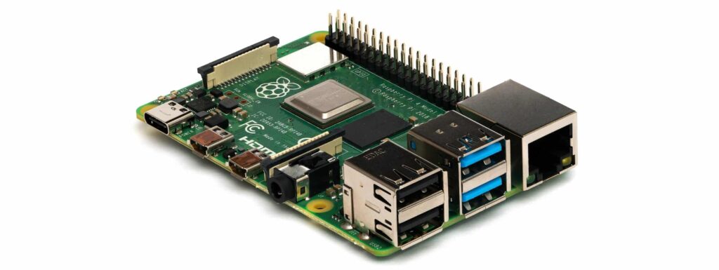
If you are looking for the results of the sbc_gpio tests, please check out our sbc_gpio Pi 4B vs Rock 5B comparison.
Configuring the sbc_gpio for the Raspberry Pi 4B test requires 1x I2C, 2x SPI, 1x UART and 2x IR (1 Tx and 1 Rx). All the configuration can be done directly in the /boot/config.txt file. Alternatively, some of the overlays may use the raspi-config tool (1x I2C, 1x SPI, 1x UART).
In all, the setup is quick and easy and only takes a few minutes. RPI does support applying overlays without a reboot, however I generally just add the configuration and reboot to apply the changes.
Raspi-config vs /boot/config.txt
The raspi-config tool is a quick and easy way to setup your Raspberry Pi SBC for some of the typical overlays, but not all overlays are exposed using this tool. For anything beyond the basics, you’ll need to edit the /boot/config.txt file directly. You can also bypass the raspi-config tool and edit the /boot/config.txt file manually for all overlays if you prefer. Where applicable I’ll show both methods for reference.
You can find a full breakdown of available /boot/config.txt file options on the Raspberry Pi website.
In the raspi-config tool, overlays can be accessed from the “Interface Options” menu:

I2C0 – 16×2 LCD display
Only the 1st I2C bus can be configured from the raspi-config tool:


Alternatively the following can be set in the /boot/config.txt file:
dtparam=i2c_arm=onSPI0 – BME280 / BMP280
This uses our dht11_spi python library that uses the input on the SPI bus in conjunction with an output GPIO pin and a transistor to trigger and read the DHT11 sensor. You can read more about the dht11_spi library here. Only the 1st SPI bus (spi0) can be configured using the raspi-config tool:


Alternatively the following can be set in the /boot/config.txt file:
dtparam=spi=on
dtoverlay=spi0-1cs
SPI1 – BME280 / BMP280
Any SPI buses after the first need to be enabled from the /boot/config.txt file directly. The following will enable the SPI1 bus with 1 CS.
dtoverlay=spi1-1csUART0 – for serial communication
The UART0 interface will be used for sending serial traffic to a CP2102 USB to serial converter. The CP2102 USB port will connect back to the SBC. No drivers are needed for the CP2102 (necessary drivers are already present in the Linux kernel).
The UART0 serial port can be enabled using raspi-config. The first question is used to enable a console port to the Raspberry Pi over UART0 (select NO). The second question enables the UART0 interface for use by applications (select YES):


Alternatively, the UART can be enabled in the /boot/config.txt file:
enable_uart=1Infrared Transmit and Receive
Infrared transmit or receive ports cannot be set using the raspi-config tool. In the /boot/config.txt file the following will enable a transmit (gpio-ir-tx) and receive (gpio-ir) pin. Replace the gpio_pin value with the appropriate number.
dtoverlay=gpio-ir,gpio_pin=23
dtoverlay=gpio-ir-tx,gpio_pin=24
You can create additional transmit or receive IR devices by simply adding another dtoverlay line with a new gpio pin number.
Summary
You will find that the Raspberry Pi platform is EXTREMELY well documented and running through the setup is a breeze. None of the overlays required any complex configuration. Most could be setup using the raspi-config wizard. There was also no need to run any update tools after modifying the /boot/config.txt file (like on some other platforms).
If you came here from our sbc_gpio test result page, feel free to jump back over to the results!
