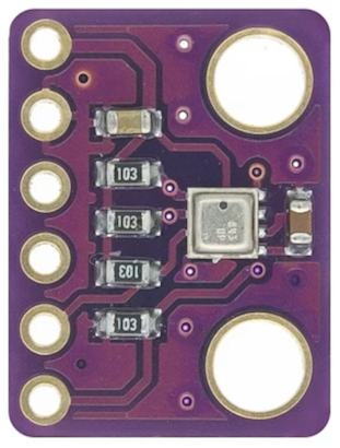
While working on my SBC comparison, in addition to building a new library to read DHT11/DHT22 sensors using the SPI bus, I had a hard time finding a working library to read BMP280/BME280 sensors using the SPI bus. Most of the libraries utilized I2C, which in normal situations would be fine. For this set of testing, I was specifically looking for a sensor using the SPI bus to verify connectivity on different platforms. So, I kicked off a mini project to build a new library.

For those unsure on whether to use SPI or I2C for a given sensor, one feature of the SPI bus that makes me tend to prefer it is the lack of bus addressing. Most I2C devices I’ve seen tend to come with pre-defined I2C bus addresses. Some devices allow you to switch the address between two different options by setting a jumper (or soldering a pad). What do you do if you need two or more of the same sensors connected to an SBC or microcontroller? SPI does require more cabling but using the CS (chip select) to identify the intended sensor allows for more flexibility. If the number of cables isn’t an issue, I’ll likely use SPI wherever possible.
Setting used by BME280/BMP280 sensors
Sensor Modes:
- Sleep Mode: Initial state after startup. No sensor readings are running, all registers are accessible and consumes the lowest amount of power
- Forced Mode: Performs one measurement of enabled sensors and returns to sleep mode
- Normal Mode: Cycles between measuring enabled sensors and inactive periods between measurements
When a “forced” read is called, the sensor will simply take a single reading and store the result. Once the reading has been taken, the raw data can be read from the register. When in normal mode, reads can be performed at any time. Any read in normal mode will return whatever current raw data is presently stored in the memory registers. With IIR filtering that will mean averaged data, or when filtering is disabled, whatever reading was taken last.
IIR Filter (aka Oversampling)
The description of the IIR filter took some time to sort out. When the IIR Filter is enabled, the “filtered” data holds an average of x number of readings. In some areas, this is called oversampling. The documentation refers to IIR filtering to “reduce the noise”. The concept here is averaging out readings to minimize brief variations in pressure or temperature. The humidity sensor does not use IIR Filtering. The IIR filter is only applicable when in normal mode. The filter also applies to BOTH the temperature and pressure sensor (there isn’t an independent filter setting for each). The filter is cleared when the sensor is placed in normal mode. After the filter is cleared, all future readings are averaged in. The higher the filter number, the lower the impact a single reading will have on the “filtered” value.
IIR filtering supports the following values: 0 (off), 2, 4, 8, and 16.
Sensor Resolution
The humidity sensor (BME280 only) always runs as a 16 bit ADC. Pressure and temperature sensors default to 16 bit when the IIR Filter is disabled and can be set to 0 (disables the sensor), 1 (for 16 bit), 2 (for 17 bit) or 3 (for 18 bit). When IIR Filtering is enabled, the pressure and temperature sensor run at a fixed 20 bit (higher resolution for averaged readings).
Standby Time
When running in normal mode, the BME280/BMP280 sensor will take readings on regular intervals. In between each reading the sensor will sleep for the “standby” time before waking up and taking another reading. When running in normal mode with the IIR filter enabled, the sensor will take readings and average the results into the stored result. The datasheet for the BME280 and BMP280 disagree on the meaning of the standby time settings somewhat. They agree on the sleep time for values 0-5 but differ on the meaning of 6 and 7.
Standby time supported values: 0 (0.5ms), 1 (62.5ms), 2 (125ms), 3 (250ms), 4 (500ms), 5 (1000ms), 6 (10ms in BME280 or 2000ms in BMP280), 7 (20ms in BME280 or 4000ms in BMP280). I’m assuming that the values in the BME280 datasheet are in error and used the BMP280 values in my library. If you want to be safe, stick with the 1 second interval or less.
How it Works
I named the library BMX280 because I wrote it to support both the BME280 and BMP280. Both read temperature and air pressure, the BME adds a humidity sensor as well (for a premium price!). Following the datasheets available from the manufacturer, it was clear that both sensors use the same set of registers and the same mechanism for sending and receiving data.
BME280 Datasheet: https://learningtopi.github.io/datasheets/bme280.pdf
BMP280 Datasheet: https://learningtopi.github.io/datasheets/bmp280.pdf
All registers on the BME280/BMP280 sensor support either a read or write operation. Configuration registers can be read or written, other registers are read only. With all this information, it was easy to create a Python library to read and write to the registers. The most difficult part by far was figuring out the trimmer parameters and how to take the raw data and convert it to usable temp, humidity and pressure data. I won’t go through all the details of the math. I’ll just say that there are 3 registers for temperature, 9 for pressure and 6 for humidity. The value in these registers holds calibration data that is burned into the chip from the factory and is REQUIRED to calculate the proper values.
Now that the structure is done, I may go on to add a background polling to keep a list of values polled while in normal mode. I can also take the SPI setup and port to I2C since the registers are the same, only the medium is changed.
Please check out our module documentation page here: </////>
Also check out our SBC comparison project that this library was written for here: </////>
