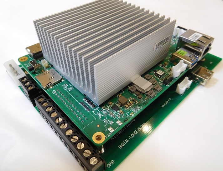
I purchased the Atomic Pi at a stellar price. Currently you can still get it for $50 at Amazon with the camera and breakout board. An incredible price for an x86_64 SBC! The Atomic Pi does have some Pros, but mostly cons. I’ll walk through what I found here.

Scoring and Specs
Here is a breakdown of the scoring. I’ll cover each section below to describe how I came to the numbers.
SBC Scoring Results
| Category | Atomic Pi |
|---|---|
| Tests – GPIO’s (1pt) | 1/1 |
| Tests – IR (1pt) | 0/1 |
| Tests – I2C (1pt) | 0/1 |
| Tests – SPI (2pt) | 0/2 |
| Tests – UART (1pt) | 1/1 |
| Subjective Performance (2pt) | 1/2 |
| Ease of Use (2pt) | 1/2 |
| Software Updates (2pt) | 1/2 |
| Community (2pt) | 0/2 |
| Overall (14pt) | 5/14 |
Scoring the SBC for comparison purposes. Scoring will be based on the following criteria:
– GPIO (1pt) – LED and button tests passed and there are at least 8 usable GPIO’s
– I2C (1pt) – I2C display tests passed
– SPI (1pt) – SPI tests passed (BME280 and DHT11 over SPI)
– UART (1pt) – UART tests passed and multiple UARTs are available
– Subjective Performance (1pt) – Was the system responsive and functional overall
– Ease of Use (1pt) – How easy was it to setup and use for the sbc_gpio tests? Can it be reconfigured quickly?
– Software Updates (2pt) – How frequently does the system get updates? 1pt for base system, 1pt for kernel
– Community (2pt) – Finding answers to questions, getting recommendations and help is an important part of using a SBC
The specifications for the Atomic Pi that I was able to collect are available below:
| Atomic Pi | |
|---|---|
| CPU | Intel Atom x5-Z8350 4 Core (480Mhz – 1.92Ghz) |
| NPU | N/A |
| Memory | 2GB DDR3L-1600 |
| GPU | Intel Integrated HD Graphics 12 execution units (200-500Mhz) |
| Video Decoding | H.263, MPEG4, H.264, H.265 (HEVC,8bit), VP8, VP9, MVC, MPEG2, VC1, JPEG |
| Video Encoding | H.264, H.263, VP8, MVC, JPEG |
| GPU FP16/FP32/FP64 | ? / 17.8 / ? GFLOPS |
| Video Out | 1x HDMI |
| Video In | 5pin webcam connector (can be used for USB 2.0) |
| Storage | 16GB eMMC MicroSD |
| USB | 1x USB 3.0 Type-A (on CPU board) 1x USB 2.0 Type-A (on carrier board) |
| PCIe | N/A |
| Networking | 1Gbps Realtek RTL8111G-CG MediaTek RT5572 2.5/5GHz/2×2 MMC connectors (requires external antenna not included) |
| Bluetooth | CSR CSR8510 |
| I2C | Software only – configurable on GPIO |
| SPI | Software only – configurable on GPIO |
| UART | 3x (fixed, GPIO pins can’t be re-purposed) |
| PWM | N/A |
| ADC (analog to digital) | N/A |
| CAN Bus | N/A |
| General GPIO / Other | 8x (6x + 2x for volume control that can be used as GPIO) + BNO055 (accelerometer, gyroscope, geomagnetic sensor) |
| Power | 5v DC 3-4A (power from 26pin connector on CPU board, or from a carrier board) |
| Kernel Support | Supports Windows 10 Digital Loggers image runs Linux 5.4 |
| Purchase Links | Amazon |
GPIO’s (1/1)
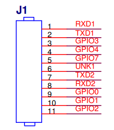
The main set of IO on the breakout board is the 11 screw terminals that connect off the 26-pin plug on the bottom of the main board. Here we have the following:
- 6x general GPIO pins
- GPIO1 and GPIO2 also connect to LEDs on the breakout board
- 2x UART (RXD1/TXD1 and RXD2/TXD2)
- These CANNOT be repurposed
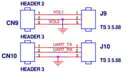
In addition to the main IO block, there are two additional 3-pin blocks on the back of the board. J9 has 2 pins for volume that can be repurposed as general GPIO’s. J10 has another UART (also CANNOT be repurposed).
I’ll note this again later with documentation, but the GPIO info listed in the official documentation appears to be wrong. The main GPIO documentation (https://download.fosc.space/atomic_pi/guide/html/gpio.html) says that the GPIO’s are on GPIO chip 3, when they are actually on GPIO chip 2. It DOES list global pin numbers that are correct, but modern Python libraries using gpiod use the Chip/Pin combo which threw my testing for a loop.
Updated GPIO Table
| Name | Chip | Pin | Global Pin | Connected Devices |
| GPIO0 | 2 | 21 | 335 | Breakout Board Green LED (active LOW) |
| GPIO1 | 2 | 18 | 332 | Breakout Board Yellow LED (active LOW) |
| GPIO2 | 2 | 24 | 338 | |
| GPIO3 | 2 | 15 | 329 | |
| GPIO4 | 2 | 22 | 336 | |
| GPIO7 | 2 | 16 | 330 | |
| GPIO_DFX_2 | 1 | 7 | 348 | Volume Up |
| GPIO_DFX_4 | 1 | 5 | 346 | Volume Down |
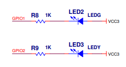
The Green and Yellow LEDs are connected to VCC3 (3.3v) and the GPIO through a 1k resistor. Using GPIO1 and GPIO2 as an input is essentially impossible as these GPIO’s will be pulled high at all times.

Major GPIO limitations:
- As noted, UART pins cannot be reused as GPIO
- There are no pull up/pull down options available (can’t say if the hardware itself is capable, there does not appear to be any way to set it using the 5.4 kernel that the Atomic Pi is running). External pull up/down must be used
- Limited numbers – only 8 total GPIO’s can be used
- GPIO1 and GPIO2 are connected to 3.3v via the LEDs which means they are usable for output only.
I am technically passing the GPIO category, since there are 8 usable GPIO’s, but the limitations make it a tough call.
IR (0/1)
Enabling the GPIO UART was relatively simple. The 5.4 kernel has compiled in a patch that exposes the ability to create and delete (although deleting is not recommended) overlays on the fly. This means we just needed to create the DTS files, compile them, then load using the following:
sudo mkdir /sys/kernel/config/device-tree/overlays/{overlay-name}
sudo cat {overlay}.dtbo > /sys/kernel/config/device-tree/overlays/{overlay-name}/dtbo
You can find copy of the DTS files as well as the application script on our GitHub: https://github.com/LearningToPi/learningtopi.github.io/tree/main/files/atomicpi
Applying the overlay was simple, however the receiver would only occasionally pick up the transmitted signal. I was a bit surprised at this but given other issues didn’t see digging deeper as necessary.
I2C (0/1)
The Atomic Pi has no hardware I2C or SPI capabilities. Digital Logger provides a software-based driver that can be used to create I2C or SPI on the limited number of GPIOs. The I2C driver uses a daemon to load overlays based on files located in the /etc/i2c-gpio-custom.d folder. There is an existing bus for the BNO055 sensor built into the board. You can’t use the I2C bus used for the BNO055, so simply create a new file and provide the parameters outlined in the README file. I used pins 476 and 480 for my SDA and SCL pins (creating a new bus 41). Simply restart the board or restart the daemon:
sudo systemctl restart i2c-gpio-customThe I2C bus shows up, and I’m able to see the device using i2cdetect. I am also able to connect to my 16×2 LCD and write content to the display! However, as soon as I loaded up the system with other tasks (in particular the IR) the number of successful writes to the I2C device plummeted. In the end a 52% success rate was all I could manage with IR enabled. Also note that due to the lack of GPIO’s, I was unable to run I2C and SPI at the same time. The best I could manage was simple GPIO in and out, UART and I2C together.
Please note that even the aged Raspberry Pi 3B+ is able to run the I2C bus with no issues since there is a hardware controller available. I have found numerous posts on the internet of people having success with I2C on the Atomic Pi, so before you call foul, your experience will vary depending on how busy the system is with other tasks. I wouldn’t depend on the software driver.
SPI (0/2)
The SPI driver works exactly the same as the I2C above. The SPI driver is configured using files in the /etc/spi-gpio-custom.d folder. Here you need to provide a bit more info. This includes a bus ID (0), CLK (335), MOSI (329), MISO (336), mode (0), max frequency (500,000), and CS pin (338). Restarting the service or the board will create your SPI bus:
sudo systemctl restart spi-gpio-customFor reasons unknown this well for my BME280 sensor with no load. Under load I saw that the reads were successful, but the BME280 sensor was reporting my office was below freezing or approaching the boiling point of water. This is most likely due to bits getting flipped or mismatches in the timing. I would say that it is hard to trust your sensor data if you are reading over a software SPI interface.
When attempting to use my DHT22 over SPI (Python dht11_spi for details if this is new for you) was a complete failure. From what I can gather, the software SPI bus is not able to process the data quickly enough.
UART (1/1)
With UART we had great success! There are 3 available HARDWARE UART ports available. Two are available on the main breakout (J1) and one on the debug header (CN10). I left the debug header as a console interface and used UART1 on the breakout.
Traffic between the UART and USB CP2102 ran perfectly in both directions. With IR running I consistently saw 98% success (out of 14760 tests). With IR disabled it went to 100%. I can say that this was a complete success and performs even better than the RPi4B did.
UART was the ONLY test that passed with flying colors.
Subjective Performance (1/2)
This category is a bit open. I have 3 possible values:
- 0: The system is extraordinarily slow. It may be functional, but performance was an issue
- 1: The system works about like we would expect from an SBC. It was not excessivly slow and booted quickly. However, it doesn’t have any “wow”.
- 2: This is reserved for the “wow” devices. So far one device (the Radxa Rock 5B) fits into this category.
The Atomic Pi boots relatively quick. The BIOS POST is certainly slower than UBOOT on an ARM device. Out of the box the Atomic Pi comes with a built-in eMMC that was significantly quicker than a Micro SD Card and gave it a bit of an edge in performance. However, the eMMC failed and left me with SD. I’ll talk about the eMMC under the problems category below.
Ease of Use (1/2)
This wasn’t hard to grade. The software SPI and I2C buses are easy to set up and use. The sysfs driver for the overlays makes adding overlays for IR easy. Since we don’t have the ability to load overlays during the boot process on x86 like we do with ARM this is a must have.
I did have to doc a point for incorrect documentation. Not having correct GPIO Chip / Pin numbers listed for the few GPIOs that are available made using the system significantly more difficult than it should have been.
Software Updates (1/2)
This was a tough category. Given the issues that I have seen of late in the IOT world, any project should be able to be maintained and updated with security patches. On the plus side, as an x86 board, the Atomic Pi can run vanilla Ubuntu or really any other distribution that you want. The DOWNSIDE is that to maintain the “ease of use” we talked about above; you need to run the Digital Loggers kernel and here is where the problem comes in. The kernel is 5.4.30 and doesn’t appear to ever get updated. Digital Loggers GitHub does NOT have a repo for their kernel either.
5.4 is a long-term release, but 5.4.30 is from April in 2020. Since it is July 2023, it seems likely that this isn’t being actively maintained. This leaves you with a choice:
- Keep the functionality for I2C/SPI and the ability to load overlays
- Keep your system up to date on a supported kernel
Community (0/2)
I was able to find others that had purchased and used this board, but don’t expect anything like the community available for Raspberry Pi products. There is really only one “community” page here: http://ehxz.tk/atomicpi. There are some downloads available with different Ubuntu / Debian images as well as BIOS files, but that’s really about it. Don’t expect a large community with examples to pull from.
Issues
During setup, testing, or normal usage I ran into a few problems.
Power Issues
I tried using Pi 4B adapters and numerous other 5V power supplies to no avail. I even tried running the power directly into the pins on the bottom of the board (bypassing the breakout). The documentation says to use MULTIPLE pins if powering directly, which made me leery. In the end I ended up using my bench power supply (an EVGA SuperNova 550 ATX power supply).
I did find several other power supplies that would work, but quickly ran into stability issues (Atomic Pi would simply lock up after running for a period of time). Once I had the power sorted out, I had no issues with locking up.
CMOS Battery
Since the Atomic Pi is basically just a small Intel computer, it has a CMOS battery. Mine was dead out of the box and resulted in a reset of the BIOS and clock every time I removed power. I couldn’t find one with a matching plug, so ended up splicing a new battery in.
eMMC
I was happy that the Atomic Pi came with a built-in eMMC. These aren’t typically super fast but are generally way faster than running from an SD card. The downside here is that my eMMC went belly up after a while and stopped being recognized in the BIOS. I followed all the instructions I found on the web and couldn’t get it back working again. Eventually I gave up and reverted to an SD card.
I suppose if I ever decide to use this device long term, I could connect an external USB to eMMC similar to what I do with the Raspberry Pi 4B. SD cards are just not fast enough to run a graphical interface. Headless systems might work well enough, but GUI’s will just slow the system to a crawl.
Overall (5/14)
Overall, I would say that the Atomic Pi performs poorly in most circumstances. There are a few use cases though that I think the Atomic Pi could really shine (particularly given the low price):
- If you MUST have x86 for software binary compatibility
- If you need to run Windows (NOTE: I didn’t test any GPIO / I2C or SPI under Windows)
- If you have a project that needs 3x UARTs and only a couple of GPIOs
Unless you fit in the use cases above, you could probably do better with another system. As I wrap up testing on a range of different platforms, I’ll add a page to compare and contrast the different systems available.


