I am currently working on a project to compare different SBC devices and compare the functionality to the gold standard, the Raspberry Pi 4B. Rather than just comparing specs, I am endeavoring to compare the GPIO functionality and support within Python. As a part of this comparison testing a grabbed a trusty old DHT11 and found that it doesn’t work as well as it used to.
NOTE: The DHT22 operates the same as the DHT11. There is a slightly different method required to read the binary data, however the data transfer is performed the same way. Other than the method to convert the binary data to a number, all references to the DHT11 can be interchanged with a DHT22.
What Has Changed?
In later releases of the Linux kernel, how GPIO’s are accessed has moved away from direct “bit-banging” (the term widely used to reference directly accessing the GPIO registers) to API interfacing through the Linux kernel. On one side this provides accounting of what applications are using which pin and helps prevent improper use. On the other hand, it adds a layer between Python and the GPIO’s.
Reference: https://waldorf.waveform.org.uk/2021/the-pins-they-are-a-changin.html
How does a DHT11 work?
The trusty old DHT11 uses a slightly unusual method of operation. There is a single data pin that is used to trigger a read from the device (by pulling the data pin low for a minimum of 18 ms). Most DHT11 devices have 3 pins on a small PCB. The 3 pin model includes a pull-up resistor. 4 pin models without the PCB need to have an external pull-up resistor added.
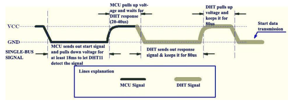
After the DHT11 device is triggered by pulling the data pin to ground, the sensor starts transmitting binary data by pulling the data pin to ground and releasing. Each bit is preceded by a 50us pull to ground followed by a 0 or 1 represented by leaving the data pin high for 26-28us for a 0, or 70us for a 1.
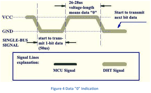
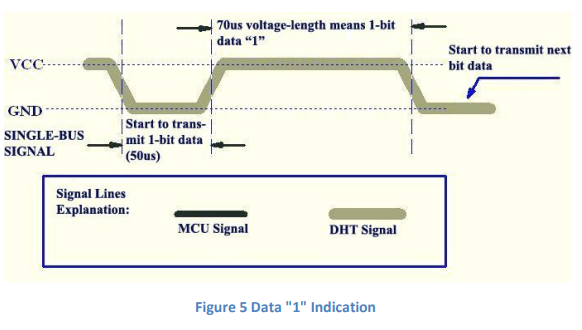
To read the data transmitted by the DHT11 sensor, the application must be able to read the difference between a high voltage held for 27us and 70us! For reference 27us is 0.000027 seconds! Or .001 milliseconds! This is an incredibly small slice of time!
The classic DHT11 library (https://pypi.org/project/dht11/) does this by simply reading the value from the data pin in a loop until it has recorded 100 concurrent values the same. The loop (https://github.com/szazo/DHT11_Python/blob/master/dht11/__init__.py) is run without any delay added, so the data is collected as fast as the Python code can run. Even at the best of times, this was only successful for me somewhere around 50% of the time. The rest of the time the code wasn’t able to read the data quickly enough. On a modern board with a modern kernel this seems to be even worse. I found it rare to EVER get a successful read. The issue comes down to the speed of switching from an output pin to an input pin, then reading the input rapidly enough to capture the high and low values.
Are all DHT11 or DHT22 sensors simply useless in modern kernel devices? Are we stuck with either old out of date devices or upgrading to more expensive I2C or SPI temperature/humidity sensors? I was determined to look for an alternative.
The Alternative for reading the DHT11 / DHT22!
After pondering the issue, I started to think about what other components on the typical SBC can read data quickly enough to measure the difference between a high voltage held for 27us or 70us. After some quick conversion on unitjuggler.com (https://www.unitjuggler.com/convert-frequency-from-%C2%B5s(p)-to-Hz.html?val=27), I realized that 27us is just over 37kHz. It occurred to me that the SPI bus is capable of running in the 100’s of Mhz range (depending on platform of course). That makes the SPI bus hundreds of times more sensitive than needed to read the DHT11!
| Part | Link | Cost (At time of writing) |
|---|---|---|
| DHT11 | At Amazon | $13.99 for 10 ($1.40/ea) |
| DHT22 | At Amazon | $13.99 for 2 ($7.00/ea) |
| 2N5551 NPN Transistor | At Amazon | $13.99 for 450 assorted ($0.031/ea) |
| 1x 470Ω resistor | At Amazon | $11.99 for 525 assorted ($0.023/ea) |
| 1x 1kΩ resistor (for voltage divider) | At Amazon | $11.99 for 525 assorted ($0.023/ea) |
| 1x 2kΩ resistor (for voltage divider) | At Amazon | $11.99 for 525 assorted ($0.023/ea) |
| Total for 1x DHT11 | $1.71 | |
| Total for 1x DHT22 | $7.10 |
As an Amazon Associate I earn from qualifying purchases. Ads and associate programs is how we pay for our content. Using our associate links supports our site!
This solves the problem of how to READ the data coming from the sensor but introduces a new problem. The SPI bus uses separate pins for CLK (used to sync the bus frequency to all devices), MISO (in from sensor), MOSI (out to sensor) and CS (used to signal to a sensor). The DHT sensor uses the equivalent of the CS and MISO on the same data pin.
My solution was to split the load between two pins. Read data on the MISO pin of the SPI bus but initiate the signal to the DHT11 to start transmitting its readings from another pin. The question was how to do this? My solution was to add a 470ohm resistor and a 2N5551 NPN transistor.
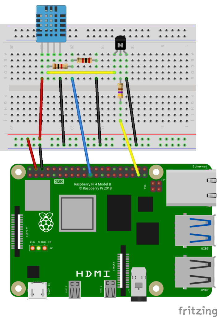
The “signal” pin is connected to the base of the NPN transistor via the 470ohm resistor (to prevent excessive current from being pulled through the signal pin). The collector leg of the NPN is connected to ground, and the emitter to the data pin on the DHT11.
When the NPN transistor is “energized” by setting the signal pin high, current is allowed to flow from the emitter to the collector which will draw the data pin on the DHT11 to ground. As long as the signal pin is kept high, the DHT11 data pin will be pulled to ground. Once the signal pin is set low again, the NPN transistor will allow the data pin to return to a high voltage provided by the pull-up resistor.
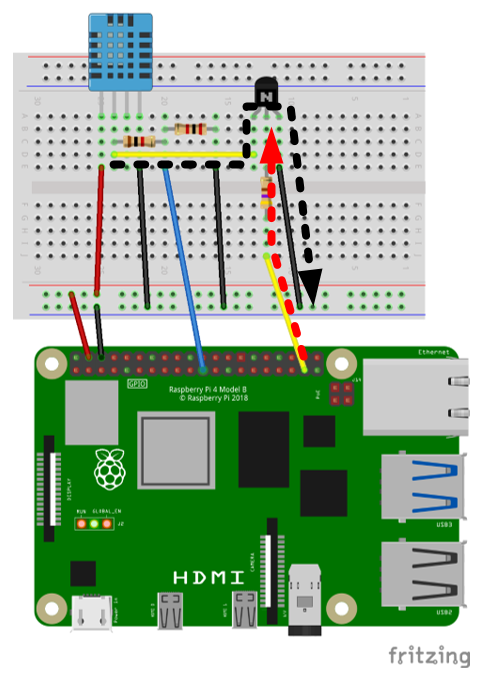
Step 1: Transistor is activated by output pin set to high causing the data pin on DHT11 to be pulled to ground (also the SPI MISO)
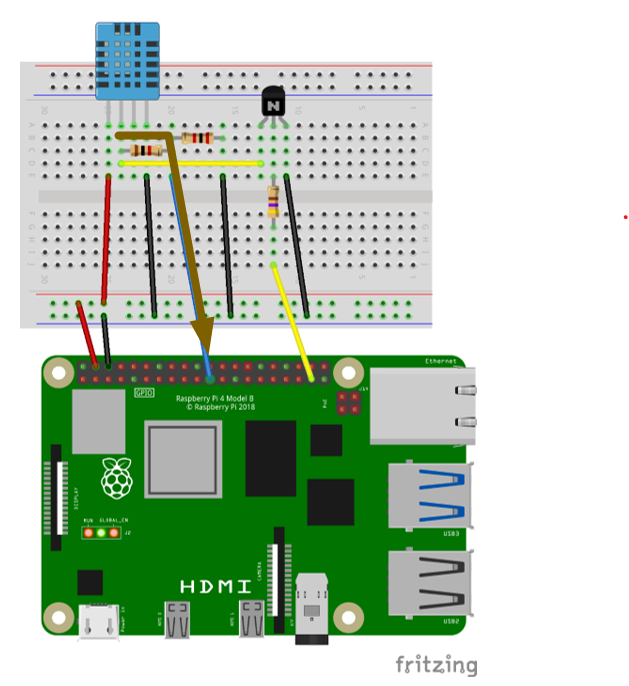
Step 2: Output pin is set back to low, DHT11 starts transmitting and data is received on SPI MISO port.
Now that we have triggered the DHT11 sensor to start sending its data, we can use the SPI bus to read the data. Python has a library spidev (https://pypi.org/project/spidev/) that can be used to set the bus frequency and read data from the bus. Then it is simply a matter of counting how many 0 and 1 bits are received and factoring in the frequency of the SPI bus to determine how many sequential 1’s are needed to represent a 0 or 1 transmitted by the DHT sensor.
Conclusion
Bit-banging is getting more and more difficult. That doesn’t however mean that there are no other (and better) ways to work with sensors like the DHT11. Using the SPI bus to read the DHT11 sensor so far has given a 90+% success rate. This is far better than the bit banging library even on the older kernels where 25-50% I considered successful. There were projects I built that read the DHT11 3 times in a row in hopes that one of them would work.
Sometimes you need to find creative ways to perform tasks. Feel free to leave a note in the comments if you make use of the dht11_spi library or create a similar library to work around the kernel GPIO limitations.
