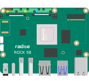
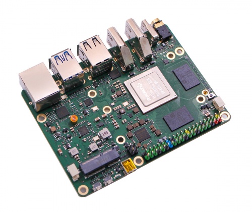
After waiting 6 months from my pre-order on Ameridroid I finally received my Rock 5B! I ordered this using early on to get my hands on one of the new 8 core (4x A76, 4x A55 Rockchip RK3588) systems. My plan is to make this my daily driver, so I ordered the system with 8GB of RAM. I was impressed with the specs that include an optional eMMC chip as well as a PCIe 3.0 x4 NVMe SSD! Let me walk you through the Rock 5B Setup


During the setup, I ran into a few issues that I’ve outlined below. All were resolved in some fashion and I have the system up and operational! At the end I’ve included some helpful links as well as some platform specific commands I’ve found that may be useful for you.
Radxa Rock 5B Highlights
| Rockchip RK3588 (4x Cortex-A76 + 4x Cortex-A55) |
| 4GB, 8GB or 16GB of 64bit LPDDR4X RAM at up to 4224Mhz |
ARM Mali-G610 MP4 3D (4 cores 300Mhz – 1Ghz per info in /sys/class/misc/mail0/device) |
| up to 8K@60 HDMI |
| 3.5mm jack with mic input |
| 2x USB 3.0 Ports, 2x USB 2.0 Ports |
| PCIe 3.0 x4 M.2 M key (on bottom of board for SSD, fits 2280) |
| PCIe 2.0 M.2 E key (on top of board for WiFi module) |
| 2.5Gbps RTL8125 NIC |
| 6T NPU supporting INT4/INT8/INT16/FP16. Per hardware datasheet, “network models based on a series of frameworks such as TensorFlow/MXNet/PyTorch/Caffe can be easily converted” |
| 40 pin GPIO – I2C, PWM, SPI, UART (See Debian guide for details to enable) |
I haven’t seen any helpful information on the NPU yet, but the hardware specs make the Rock 5B a potential candidate as a desktop PC replacement.
Parts List
| Part | Link | Cost (at time of writing) |
|---|---|---|
| Radxa Rock 5B (8GB) | At Ameridroid | $169.95 |
| Crucial P3 500GB PCIe Gen3 NVMe SSD (optional) | At Amazon | $34.99 |
| M.2 SSD Heatsink (optional) | At Amazon | $10.99 |
| 64GB eMMC (optional) | At AliExpress | $39.98 |
| Heatsink | At Amazon | $11.99 |
| Total (with options) | $267.90 |
As an Amazon Associate I earn from qualifying purchases. Ads and associate programs is how we pay for our content. Using our associate links supports our site!
Issue #1 – Initial Power Problems
All the way up to when I received my Rock 5B, there were no official accessories I could find for purchase. That meant that I was going to use an available power supply and my own heat sink. Immediately I wrote the Debian image onto an SD Card, plugged in a Lenovo USB-C PD power supply and let it rip. I was met with what appeared to be a boot loop (based on the LED indicators). Disappointed I tried an RPI-4B 5v USB-C power cable, and still got nothing.
From Radxa’s page, I saw that there is a serial debug port (https://wiki.radxa.com/Rock5/dev/serial-console), so I connected a CP2102 USB to UART module I had to the serial port. Radxa’s page called out that these adapters often don’t support the 1.5Mbps data rate that they set their UART port to (why 1.5Mbps?), but figured it was worth the shot.
Oddly enough after connecting a CP2102 USB to UART, even though I was getting gibberish (likely due to the date rate issue) the board booted into Debian! I scratched my head but decided to press on and come see if I could figure out what was going on later. Debian would work, but if I disconnected the serial debug port on the next reboot, I would go back into the reboot loop.
Armed with some more information, I found a thread on the Radxa forum (https://forum.radxa.com/t/rock5-does-not-work-on-most-pd-power-supplies/12042/6) that called out similar issues and confirmed that connecting the debug port seems to resolve the boot loop issue by triggering a brief delay in the boot process.
Now that I was able to confirm the issue, and with a deeper read of the thread I also discovered that there were issues with different USB-C PD supplies as well. I decided the best next step was to update the SPI flash on the board since my board must have been in one of the early manufacturing runs.
Updating the Rock 5B Flash
Radxa has a documented process for updating the flash (https://wiki.radxa.com/Rock5/install/spi) that I read over and over and still wasn’t entirely clear on what was needed. My guess is that there is a bit lost in translation here, so here is a detailed list of the steps that I used:

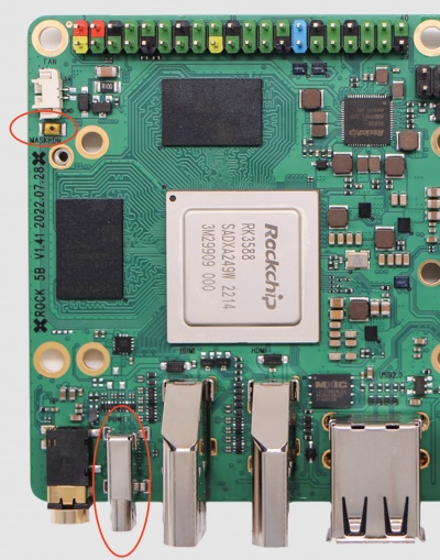
- Connect the board to my Raspberry Pi 4B using the USB-C port (make sure you have a powered USB hub! Hold down the Maskrom mode button (see the image (taken from Radxa’s page).
- Verify that the Pi 4B sees the USB device using “
lsusb”. You should see “Bus 001 Device 112: ID 2207:350b Fuzhou Rockchip Electronics Company” listed in the output. If not, check your cable, make sure you have a powered USB hub or are connected to a PC with sufficient power. - Since I am using a Pi 4B running Raspbian I had to install the rkdeveloptool (install outlined here https://wiki.radxa.com/Rock5/install/rockchip-flash-tools):
sudo apt-get install libudev-dev libusb-1.0-0-dev dh-autoreconf
git clone https://github.com/radxa/rkdeveloptool.git
cd rkdeveloptool
autoreconf -i
./configure
make- Download the SPI image (link available on https://wiki.radxa.com/Rock5/install/spi). There are two files that are needed. The “RK3588 loader” (labeled as a USB flashing helper), and the SPI image itself. There are 3 different SPI images available. The release version has serial console disabled and the debug with it enabled. There is also an Armbian specific version which I am ignoring here. Given my power issues I wasn’t sure if I needed the console enabled or not. I can tell you that the “release version” has worked perfectly so far.
- Use the rkdeveloptool to flash the image:
sudo rkdeveloptool db [rk3588 loader file]
sudo rkdeveloptool wl 0 [spi “release version” image]
After the flash, I found that I could reliably boot with both USB-C PD power supplies as well as a 5v adapter!
1st problem solved.
Issue #2 – The next power problem
Now that I have the board booting consistently, the next step was to move over to the Ubuntu image that Radxa has available on their GitHub page (https://github.com/radxa/debos-radxa). GitHub seems like an odd place to use for a repo, but I’ll run with it. I grabbed the latest release at that point named “rock-5b-ubuntu-focal-server-arm64-20221122-0942-gpt.img.xz”. Sadly, they only have Ubuntu 20.04 images and not a 22.04 image available. I may work on creating my own release of 22.04 later.
Booting Ubuntu on the SD Card worked fine, so I installed the eMMC card that I had purchased from AliExpress (because the eMMC to micro-SD adapter I got with it wouldn’t work) and quickly discovered that the board wouldn’t boot with the eMMC if I was running on a 5v power supply. Interesting but worked with USB-PD so I filed it away and continued. Booting from the SD card I was able to see and flash the Ubuntu image to the eMMC, but on the next reboot found that the SBC boots of the SD Card first. Remove the bootable SD Card and success!
Next was to install the M.2 SSD and install the image (using the same process booting off the SD card), and again found that the SD card was preferred over the M.2 SSD for booting, but I was able to boot successfully. I also found that the board wouldn’t boot with 5v power if the M.2 SSD was present.
After more reading in the Radxa forum (https://forum.radxa.com/t/rock5-does-not-work-on-most-pd-power-supplies/12042/6), I learned a bit more about the power input on the Rock 5B and discovered that the input can be 5-20v and doesn’t technically need to be managed by the USB-PD function. The board has a buck-converter, so as long as you supply 5-20v input on the right pins on the USB-C port it will run. I was able to confirm with a 12v power supply connected using a 5.5mm barrel to USB-C adapter.
This led me down the path of testing the different combinations of SD, eMMC and M.2 SSD to see what worked.
NOTE: For all the tests 5v power is provided by a bench ATX PSU that can supply up to 20 amps on the 5v rail. I’ll use this for all my tests due to constant problems I’ve had with other SBC’s that are power sensitive. The ATX PSU provides a steady 5.2v regardless of the load I’ve been able to put on it to date.
All tests were performed AFTER the flash update!
| SD Only | eMMC Only | M.2 Only | SD & eMMC | SD & M.2 | SD & eMMC & M.2 | |
| 5v | OK | Boot Loop | Boot Loop | Boot Loop | Boot Loop | Boot Loop |
| 12v | OK | OK | OK | OK | OK | OK |
| USB-C PD | OK | OK | OK | OK | OK | OK |
What have we learned? Don’t use a 5v power supply. It is obviously limiting the capability of the device. Even with amperage form the power supply as a non-issue (using the bench ATX PSU with 20a 5v output), the board would not boot with an eMMC or M.2 SSD installed.
I’ll call this problem solved. I don’t have a lot of spare USB-PD PSUs, but I do have 12v adapters that I can easily repurpose. One important not here, if you run the “sensors” CLI command it will report 5v if you are using a 12v adapter. It appears that this sensor only pulls negotiated voltage from the USB-PD process and falls back to 5v:
USB-C PD Power Supply (from ‘sensors’ CLI utility)
tcpm_source_psy_4_0022-i2c-4-22
Adapter: rk3x-i2c
in0:    20.00 V  (min = +20.00 V, max = +20.00 V)
curr1:  2.25 A  (max =  +2.25 A)
12V Power Supply with 5.5mm to USB-C adapter (from ‘sensors’ CLI utility)
tcpm_source_psy_4_0022-i2c-4-22
Adapter: rk3x-i2c
in0:     5.00 V  (min =  +5.00 V, max =  +5.00 V)
curr1:   1.50 A  (max =  +1.50 A)
UPDATE: On the Radxa forum, I did find a command that can be used to check the actual power supply voltage that does appear to present the correct value:
$ awk '{print $1/172.5}' </sys/bus/iio/devices/iio:device0/in_voltage6_raw
12.3884
Issue #3 – The Boot Order
While running through the power tests above, I noticed that the boot order seems backwards of what I would expect:
- Micro-SD
- eMMC
- M.2 SSD
I would generally think booting from the M.2 SSD is preferred, but I did confirm that a non-bootable MicroSD card doesn’t prevent the system from booting off eMMC or M.2.
I ended up selecting the eMMC to use as my primary simply because the performance was sufficient (I’ll run some tests on it later) and it has enough storage for what I need at the moment (64GB). Even with my dev tools and other software installed, I’m still only using 29% of my usable storage. Anyway, I had a case issue with my M.2. (More on that next)
I’ll call this solved, simply because I know the order. It would be nice to set this somehow though…
Issue #4 – The Case
When I ordered there were no cases available for order when I put in my pre-order (way back in May 2022), or even when I received my board (Nov 2022). As of now, Ameridroid has a metal case that you can pre-order (https://ameridroid.com/products/rock-5b-metal-case?_pos=1&_sid=59d9c8fb8&_ss=r). Like my Atomic Pi, what is the use of a system that I have no case for? Can’t just leave it sit on an anti-static bag forever.
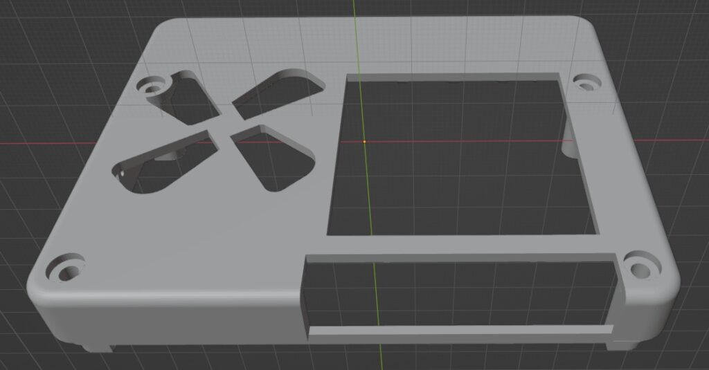
I found an STL file for a case on Thingiverse (https://www.thingiverse.com/thing:5594048) and printed it out. I found that I had a few issues with the case that I needed to fix:
- The 5.5mm barrel to USB-C adapter I’m using for my 12v power supply is too wide for the space
- The generic heatsink I purchased was larger than the opening on the top of the case, so I couldn’t get the cover on
- There wasn’t sufficient space under the SBC in the case for my M.2 SSD with a heatsink on the SSD
- The small opening for the 40 pin GPIO header is just WAY too small to be usable
This was a good excuse to learn Blender and edited the STL files from Thingiverse to create my own files. You can download my edited files below if you have similar case issues or just want to edit further.

- Case Top
- Blender source file: https://download.learningtopi.com/rock5/rock_5_top_updated.blend
- STL File: https://download.learningtopi.com/rock5/rock_5_top_updated.stl
- Case Bottom
After printing my updated files (several times as I learned the ins and outs of creating in Blender) success! I now have a case that I can use my 12v power supply with, fits my heat sink, and will fit my SSD.
That took care of all my hardware issues. Next was getting the software setup. I’ll save that for my next post. Check back to the Rock 5B category for more updates!
Helpful Links
Hardware info: https://wiki.radxa.com/Rock5/hardware/5b
SPI Flash: https://wiki.radxa.com/Rock5/install/spi
Rockchip Flashing Tool: https://wiki.radxa.com/Rock5/install/rockchip-flash-tools
Debian Guide (has dtoverlay information that is applicable for Ubuntu as well): https://wiki.radxa.com/Rock5/guide/radxa-debian
Rock 5B Platform Output / Info
Reading the spec sheets gives a lot of useful info, but until you are on the system itself there is a lot you don’t really get to see. Here is some output that will hopefully provide some useful data:
CPU Info
We know that there are a total of 8 cores, however what I DIDN’T know was that they are grouped in 3 packages. The list of /sys/firmware/devicetree/base/cpus/cpu-map shows the 3 clusters. Cluster 0 has 4 cores and both clusters 1 and 2 have 2 cores each. If we dig into /sys/devices/system/cpu/cpu0/cpufreq, we see that in the contents of the affected_cpus file that cores 0-4 use the same clock setting.
There are several options of tools you can install to gather current CPU frequency info. I’ll stick with a Python module called psutil since I will be using that for some comparisons later, and I know it is compatible across platforms.
The psutil module is available on PyPi:
pip3 install psutilWe can get the min, max and current CPU frequency info using the psutil.cpufreq(percpu=True) function.
$ python3
Python 3.8.10 (default, Nov 14 2022, 12:59:47)
[GCC 9.4.0] on linux
Type "help", "copyright", "credits" or "license" for more information.
>>> import psutil
>>> from pprint import pprint
>>> pprint(psutil.cpu_freq(percpu=True))
[scpufreq(current=408.0, min=408.0, max=1800.0),
 scpufreq(current=408.0, min=408.0, max=2400.0),
 scpufreq(current=408.0, min=408.0, max=2400.0)]
Here we can see the 3 packages. Based on this output it appears that the first cluster is for the 4x A55 cores runs between 408 and 1800Mhz. The 4x A76 cores appear to be split between the other two clusters and run between 408 and 2400Mhz. This also means that each pair of A76 cores can have their clock adjusted independently.
Temperature Sensors
There are a few options to get the temperature sensor info. During the power supply testing I used the sensors CLI utility to gather the voltage information. This tool can also be used to capture temperature data:
$ sensors
gpu_thermal-virtual-0
Adapter: Virtual device
temp1:        +35.2°C

littlecore_thermal-virtual-0
Adapter: Virtual device
temp1:        +35.2°C

bigcore0_thermal-virtual-0
Adapter: Virtual device
temp1:        +35.2°C

tcpm_source_psy_4_0022-i2c-4-22
Adapter: rk3x-i2c
in0:           5.00 V  (min =  +5.00 V, max =  +5.00 V)
curr1:         1.50 A  (max =  +1.50 A)

npu_thermal-virtual-0
Adapter: Virtual device
temp1:        +35.2°C

center_thermal-virtual-0
Adapter: Virtual device
temp1:        +34.2°C

bigcore1_thermal-virtual-0
Adapter: Virtual device
temp1:        +35.2°C

soc_thermal-virtual-0
Adapter: Virtual device
temp1:        +35.2°C  (crit = +115.0°C)

$
We can see here we have quite a few sensors available. GPU, BigCore0, BigCore1, LittleCore, NPU, and SoC. Interestingly there is only a critical temp defined for the SoC sensor and not for the NPU, CPU or GPU.
We can also use psutil in Python:
>>> import psutil
>>> from pprint import pprint
>>> pprint(psutil.sensors_temperatures())
{'bigcore0_thermal': [shwtemp(label='', current=34.23, high=None, critical=None)],
 'bigcore1_thermal': [shwtemp(label='', current=35.153, high=None, critical=None)],
 'center_thermal': [shwtemp(label='', current=34.23, high=None, critical=None)],
 'gpu_thermal': [shwtemp(label='', current=34.23, high=None, critical=None)],
 'littlecore_thermal': [shwtemp(label='', current=35.153, high=None, critical=None)],
 'npu_thermal': [shwtemp(label='', current=34.23, high=None, critical=None)],
 'soc_thermal': [shwtemp(label='', current=34.23, high=115.0, critical=115.0)]}
>>>
GPU / NPU
I haven’t found many useful builtin methods to gather GPU info. There are some files in the sys folder that can be used to output some useful info for both the GPU and NPU:
$ cat /sys/class/devfreq/fb000000.gpu/available_frequencies
1000000000 900000000 800000000 700000000 600000000 500000000 400000000 300000000
$ cat /sys/class/devfreq/fb000000.gpu/cur_freq
300000000
$ cat /sys/class/devfreq/fdab0000.npu/available_frequencies
300000000 400000000 500000000 600000000 700000000 800000000 900000000 1000000000
$ cat /sys/class/devfreq/fdab0000.npu/cur_freq
1000000000
$ cat /sys/firmware/devicestree/base/npu@fdab0000/compatible
rockchip,rk3588-rknpu
$ cat /sys/firmware/devicestree/base/npu@fdab0000/power-domain-names
npu0npu1npu2
Based on the info above, it looks like the NPU is a 3 core setup running at up to 1Ghz. I don’t have anything setup yet to test the NPU functionality but will look into that for the future.
UPDATE: From the Radxa forum I found that there is a way to get the GPU utilization:
$ cat /sys/devices/platform/fb000000.gpu/utilisation
0
Wrap Up for the Rock 5B Setup
After working through a couple of power related issues and getting the SPI flash updated the Rock 5B has been running strong. The system is extremely fast and so far seems to be a usable desktop replacement. I have run into some memory issues which I will cover in my next post on the software setup.
Keep an eye out for future posts on our Rock 5B!

It also works with 9v 2a, some usb adapters let do so.
There is also custom 22.04 Ubuntu already. But it got problems with native 4k Radxa camera.
Hi, I’m following your instructions on how to get my Rock 5B up and running without the dreaded boot loop.
You eventually got things “stable” with a 12V “brick” adapter. At the end of the adapter, is a 5.5mm / 2.1mm barrel. I have several of these I would like to use. Which 5.5mm/2.1mm barrel to USB-C adapter did you use? I’m seeing some with 5V 500mA max.
I was also thinking of grabbing a USB-C breakout board and hard-wire the 12V to the correct pins in the USB-C breakout (a breakout board with terminal screws would be ideal).
Thanks for your question! I had a 5.5mm to USB-C that I received with this power supply: https://www.amazon.com/gp/product/B08VRZJV7B/ref=ppx_yo_dt_b_search_asin_title?ie=UTF8&psc=1. This device was rated for 4amps 5v, so while the adapter itself doesn’t reflect a max amperage I have had no issues and the adapter doesn’t heat up at all. If you are concerned with the capacity of the adapter, you could always use it temporary to get the device booted and flashed, then switch to a USB-PD adapter after the update. My Lenovo USB-PD works perfectly.