Overview
Latest code is available on GitHub, View the other articles in the load testing series
This project is part 1 of 2 to capture current data for our load testing. The ESP32 microcontroller will be used as a sender, and another system as a receiver. Initially the devices will need to be connected via a serial connection, however for a future update TCP based communication may be used. Due to space constraints, the microcontroller will not store any of the collected data (beyond what is needed to calculate the current.


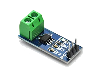
Data is sent to the microcontroller from the ACS712 based current sensor. This sensor will read a range of –20A to 20A (current flowing in either direction) and will match this to a 0 – 5V output. This means that 0A (no current flowing) will output 2.5V. All ESP32 microcontrollers support a maximum input of 3.3V on GPIO pins, so we need to ensure that traffic is flowing in the “negative” direction which will result in voltage ranging from 2.5V to 0V for 0A to 20A of current.
The ESP32 uses as 12bit ADC, which will return a value of 0-4095 depending on the input. Due to the nature of the sensor, the reference voltage for ADC is actually 1.0-1.1V, so in order to read up to 2.5V, we need to give the microcontroller an attenuation setting. The manufacturer recommendations can be found here. We will use the max attenuation setting of 11dB to support a “suggested range” of 150-2450mV.
The math to calculate the amperage draw from our ADC reading will look like this:

ADC represents the reading from the microcontroller in the range of 0 – 4095. 3.3 represents the voltage when the reading is 4095.

Here we will take the voltage reading from above, multiply it by the max amperage of the ACS712 sensor (20A), and divide by the voltage that represents the 0 Amp level (2.5v).
Putting it all together into a single expression (to simplify code of course), we get the following:

A nice simple equation with a single input and a single output. We need to account for noise and inaccuracy of the current sensor itself. To make sure our 0A level is correct, we will want the code to “initialize”, or get a reading over a period when there is no load present. This will give us a good starting point to ensure that the output from the ACS712 is accurate. We also need to account for outliers that will skew our data, so for every amperage reading, we will average the last 5 readings (taken at the configured interval of 100ms), then discard the highest and lowest values before taking our average. This method smooths out the data and will hopefully help eliminate inconsistent readings.
Espressif’s documentation notes that the ADC’s can be susceptible to noise and recommends a 100nF bypass capacitor to the input. The documentation provides a chart showing an example of raw readings, readings with the capacitor, and adding sampling.
Parts List
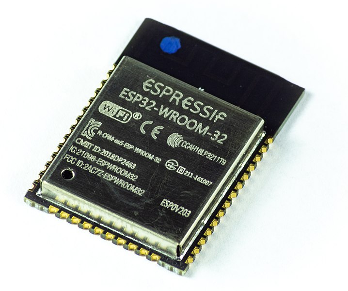
- ESP-WROOM-32D chip (bare chip) – $9.99 for 2x (only using 1)
- AAQ-CYL-GY17100 – ESP-WROOM-32 test board – $17.99
- ACS712 based 20A current sensor – $11.58 for 2x (only using 1)
- CP2102 USB to TTL adapter – $8.29 for 2x (only using 1)
- Various cable (from stock)
- 100nF ceramic capacitor – $12.99 for 600 capacitors of 24 different sizes
The ESP32 microcontroller we are using is an ESP-WROOM-32D with the following specifications:
ESP-WROOM-32D Specifications
| ESP-WROOM-32D | |
|---|---|
| CPU | Dual Core 240Mhz 32bit Xtensa LX6 |
| Co-Processor / Accelerators | AES/SHA2/RSA/ECC/RNG acceleration + low-power co-processor |
| Boot ROM | 448KB |
| SRAM | 520KB |
| SPI Flash | 4MB |
| Wireless | 802.11b/g/n up to 150Mbps (integrated antenna) |
| Bluetooth | 4.2 with BLE |
| Serial Connectivity | 4x SPI, 2x I2C, 2x I2S, 3x UART |
| Analog-Digital-Converter (ADC) | Up to 18x channels of 12bit ADC |
| Digital-Analog-Converter (DAC) | 2x channels of 8bit DAC |
| PWM | 1x motor PWM, up to 16x channels LED PWM |
| GPIO | 34 programmable GPIO’s |
We will do a follow up deep dive on the ESP32 in a later article with other Micropython compatible microcontrollers. For now, we will be using the ESP32 with 2x UART interfaces, and 1x ADC to monitor amperage on our SBCs for our load testing.
Cabling

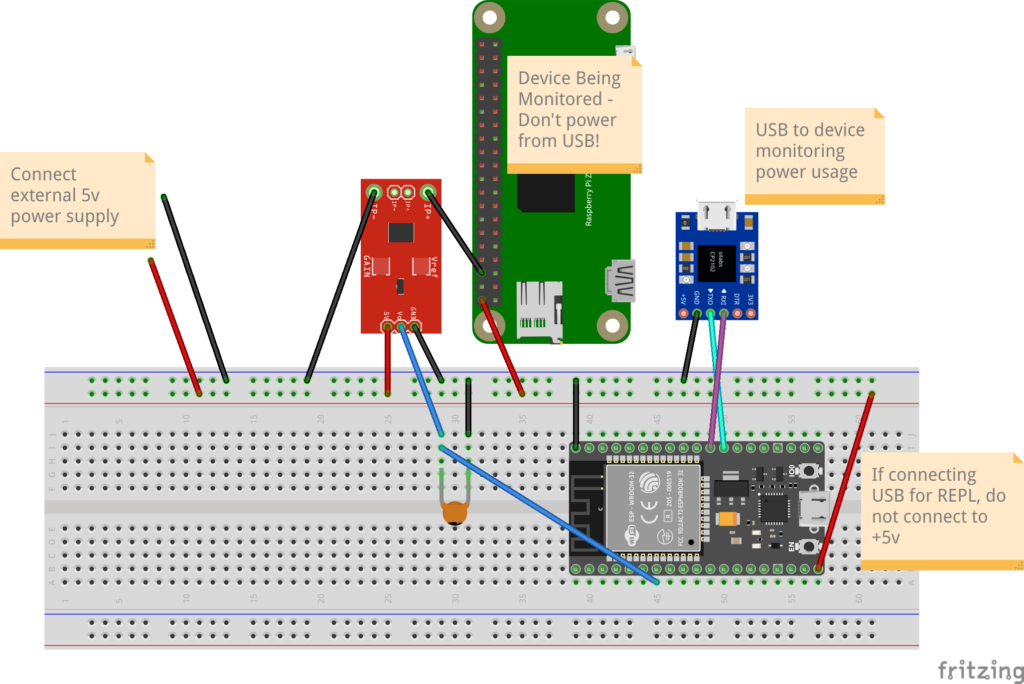
The cabling for this project is relatively simple. We have a single current sensor with a 5V input, ground and output on the Dupont pins. On the other side of the sensor are two screw jacks. The recommended configuration is to wire the ground from the device we are monitoring to one of the screw terminals, and the other to your main ground. Since we need to make sure we are reading “negative” amperage on the sensor, we need to be sure that the cables are connected such that the reading with be from 2.5V – 0V rather than 2.5V – 5V. Readings over 3.3V may fry your ESP32!
I call out using an external 5v power supply. This is needed to supply power to the device we are monitoring (a Raspberry Pi Zero in the diagram, however it can be any 5v device). The ESP32 should only be connected to the +5V of the external power supply if you are NOT using the USB port. If you are using the USB port, do NOT use the +5V cable to the ESP32, otherwise you may damage the ESP32. Technically the CP2102 is only required if the device you are connecting to does not have UART pins, however for simplicity I added the UART to USB converter to simplify monitoring the boot of Raspberry Pi or Atomic Pi SBCs.
Coding
After finishing the cabling, the next step is to load Micropython on the microcontroller. The current release is 1.18. Most ESP32’s will ship with Espressif’s AT binary installed. We will need to replace this with the micropython code before we can start programming in micropython.
Download the micropython binary for the appropriate board from here: https://micropython.org/download/esp32/. Be sure to get the binary that matches your specific board. ESP32 boards are different from ESP32-S3, ESP32-C3, etc. We are using 2022-01-17 build of 1.18
Flash the binary to the microcontroller. There are several tools you can use to do this, including a Windows based GUI flash tool from Espressif (downloadable from Espressif). We will be using the python flash tool from Ubuntu 20.04.
The python flash tool can be installed via PIP using “pip3 install esptool”
From there we can follow the instructions on the Micropython site to erase the flash and install the micropython binary.
esptool.py --port /dev/ttyUSB0 erase_flash esptool.py --chip esp32 --port /dev/ttyUSB0 write_flash -z 0x1000 esp32-20220117-v1.18.bin From here a reset of the ESP32 will reboot and start micropython on the microcontroller. You will need to connect to the console using minicom (or another terminal emulator) or you can use VSCode with the Pymakr extension (look for an upcoming article about setting this up).
Micropython uses two different files during startup. Boot.py runs first and can be used to initialize any required components. The following boot.py file specifies the configuration JSON file that will be used, sets the CPU clock to the max frequency, and outputs some version and temperature data. You should also note adding the ‘/lib’ folder to the system path.
boot.py
https://github.com/LearningToPi/adc_amerage/blob/main/esp32/boot.py
# boot.py - runs on boot-up
import os
import re
import sys
import machine
import esp32

config_file = 'config.json'
machine.freq(240000000)
print('==============================')
print('Booting...')
print('    ' + re.sub(', ', '\n    ', re.sub("[()']", "", str(os.uname()))))
print(f"CPU Freq: {machine.freq() / 1000 / 1000 } Mhz")
print(f"Internal Temp: {esp32.raw_temperature()} deg F")
print('==============================')
sys.path.append('/lib')
This will print the following output on startup:
==============================
Booting...
    sysname=esp32
    nodename=esp32
    release=1.18.0
    version=v1.18 on 2022-01-17
    machine=ESP32 module with ESP32
CPU Freq: 240.0 Mhz
Internal Temp: 117 deg F
==============================
This code prints out some useful information regarding the platform and code level, along with the current CPU frequency and tempeture of the microcontroller on startup. I personally use this as a check to ensure that my microcontroller is running the release I am expecting.
The boot.py file is also useful for setting any platform specific settings that are needed prior to launching your code. For example I am setting the frequency of the CPU to the max (240Mhz) for the ESP32 during boot. I am also using the boot.py file to add the ‘/lib’ folder to the sys path. This will allow importing of classes later.
main.py
https://github.com/LearningToPi/adc_amerage/blob/main/esp32/main.py
After the boot.py file completes, micropython then looks for and executes the main.py file. The following is an extremely basic main.py file that imports the class I will be using for this project and initializes it. All other work is done within the class which I will break down later.
from adc_amperage import AdcAmperage

# initialize the controller
sensor = AdcAmperage()
sensor = AdcAmperage()
The “adc_amperage.py” file is in the ‘lib’ folder that we added to the system path in the boot.py file. I am a big proponent of reusable code, so the AdcAmperage class inherits another class BaseESP32Worker from the esp32_controller.py file also in the lib folder. This class provides all the basic tasks of connecting to WiFi, connecting to an MQTT server (not used in this project, but will be used in future). I will break down the code for the AdcAmperage class, however I will leave the BaseESP32Worker and other supporting libraries for another topic.
/lib/adc_amperage.py
This file contains all the code specific to this project. It is rather lengthy so I will provide a summary of the functions below:
run()
This functions setups up the ADC (analog-digital-converter) pin as well as the UART used for serial communication to the receiver. We also set some variables that will be used to hold stop times for tasks once they are started. Prior to kicking off the main_loop() function, we set the CPU frequency to 80Mhz until an event comes in that needs processing. The main_loop() is called as an async function. Starting the async main_loop() function with the asyncio.run() command starts our async function and holds execution in the run() function until the main_loop() completes (which it never will unless there in an error).
async main_loop()
Main loop is a simple loop to check for commands on the UART interface from the connected device. This loop parses the received data, matches it to a supported command, then kicks off an event based on the command and options received.
- CMD:LIST – the main loop will immediately reply back with the supported commands
- CMD:INIT – creates an async task to initialize (aka baseline) the ADC sensor. create_task(…) starts the called function to run concurrent with the main loop.
- CMD:STATUS – the main loop will immediately reply back with the current status information (by calling the get_status property)
- CMD:CONFIG – the main loop will immediately reply back with the current config (by calling the get_config property)
- CMD:INTERVAL:x – the main loop will update the interval (ms between samples) based on the received value
- CMD:START[:x] – the main loop starts the function to sample the ADC sensor in a new thread, rather than using async. In micropython, a thread will run on a separate CPU core (unlike a thread in CPython). Here you will see the _thread.start_new_thread(…) function used.
- CMD:STOP – calls to stop any sampling that is currently running. This is done by adjusting the stop time variable in the class to now. After the next loop this will cause the running thread to stop (since it checks the current time against the stop time with every loop)
- CMD:ONE – makes one read of the sensor and returns the value
At the end of the loop, a critical compoment is to call sleep from the uasyncio class. Async processing runs differently than threading in CPython. With async, processing will continue until there is a pause in processing that specifically releases control. With threading in CPython, threads can move in an out of control based on when they are ready to process data. Calling sleep from the uasyncio library releases control to any other threads that need CPU time.
NOTE: With async processing, we are requesting a sleep of 100ms, however it is not guaranteed to be exactly 100ms. After the 100ms wait is over, the thread will notify the system it is ready to begin processing again, however the thread will need to wait until whichever thread is controlling the CPU to complete or release control. It is critical that any long running async function has points where it can release control, otherwise other async threads won’t ever be able to run!
property: get_status
This function returns a string displaying the current status of the microcontroller and sensor. The return can be NOINIT (not yet initialized), INITIALIZING (currently running initialization), READY (ready to start sampling) or RUNNING (currently running a sampling job). If the status us INITIALIZING or RUNNING, it will be followed by an integer with the number of seconds until it completes.
property: get_config
This function returns the current running configuration of the microcontroller.
CONFIG:{interval}:{timeout for a run}:{baseline time}:{pin #}:{name of pin}:{baseline value}
async baseline_ammeter()
This function runs a baseline on the ADC current sensor. The intent it to get a 0amp value by sampling the sensor for a period of time. This function is running async, so at the end of the loop is a call to sleep using the uasyncio sleep function.
You’ll also notice a gc.collect() call here. On each loop, the function is appending a new value to the list. During testing, I kept running into memory allocation errors at this point in the program. I was unable to verify, but suspect that micropython is copying the array and adding the new value to the end, rather than adding in place with pointers. Micropython will periodically run garbage collection to free RAM, however it wasn’t running quickly enough to keep the memory clear for subsequent loops. Adding a garbage collect after appending a value to the list resolves the memory issues.
(_thread) start_sampling()
This function performs the main data collection. The microcontroller doesn’t need to maintain data during the sampling like it does during initialization (data is just sent out to the receiving device), so we can avoid the memory issues from the initialization function. Since we want to average reads, and then discard the highest and lowest value, we are going to create a small list based on the number of reads we are configured to average.
With each read we are doing the following:
- Getting a count of milliseconds from the start (using the ticks_diff function since the ticks value can loop over)
- Calculating the amerage (by passing the relevant data to a function to perform the calculation)
- Saving the amerage in a list discussed above using the % operator. This is the python “remainder” operator and we will use that to place the amerage reading the just recorded into the list. % operates by dividing the two numbers, but returning the remainder of the division. So if the current read count is 6 and the avg_count is 5, the remainder will be 1. This will allow us to use the list with 5 values and just loop over the list replacing values. We will always have the last 5 reads (although not in any particular order).
- In order to use the list sort() function, first we need to copy the array since sort() will sort the array in place, and changing the order will mess with the previous step. After sorting we are using the log_temp[1:len(log_temp)-1] line to drop the first and last value (smallest and largest after the sort).
- The data is written out the UART interface with the average from the previous step (after dropping the largest and smallest value)
You may notice the sleep at the end of the loop is NOT using an asyncio sleep. This is because the sampling function is running in a different thread on a different core on the microcontroller, so there is no need to release control for another thread.
async stop_sampling()
This function simply adjusts the stop time that that the start_sampling() function is checking at the start of every loop. The stop_sampling thread will wait for two intervals and verify that the sampling has indeed stopped. If for some reason the sampling is still showing as running, an error is returned.
async read_ammeter()
This function will perform a single read of the sensor. A single read will still take “x” samples (5 by default) using the same process outlined in the start_sampling() function. An average of the values is returned after dropping the largest and smallest reading. This function is running async on the main thread, which means it can run concurrent with the start_sampling() function if needed.
_calc_amperage(adc_read, adc_baseline, max_amp, zero_voltage)
This function performs the calculation. The actual calculation is a single line and technically could be placed inline in the start_sampling() funciton, however the same calculation is used in the read_ammeter() function. Past experience reminds me that it is very easy to forget updating an equation if it is used in two separate places. By placing the calculation in a standalone function, any adjustments that may be needed would only need to be done in a single place.

2 thoughts on “Micropython ADC Current Sensor”