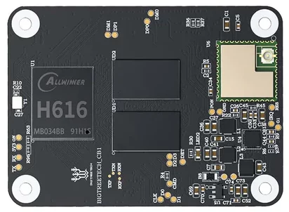
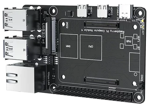
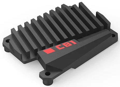
I picked up the Bigtreetech CB1 (CM4 compatible) along with their Pi4B adapter (base for the CB1 or the Raspberry Pi Compute Module 4) for a stellar price. They are currently selling the CB1 module with the Pi4B for $36.98. Even though it only has 1GB of RAM, I figured it was worth a shot so I ordered it along with the $5.90 heatsink (which I discovered is a necessity).
I’ll walk through what I learned with this device and show some of the use cases it may come in handy, as well as where some of the shortfalls are.
Scoring and Specs
Here is a breakdown of the scoring. I’ll cover each section below to describe how I came to the numbers.
The specifications for the CB1 that I was able to collect are available below:
NOTE: The Pi4B carrier board has capabilities that the CB1 doesn’t (i.e. a Gigabit NIC). The specifications are specific to the CB1 itself.
| BIGTREETECH CB1 w/ Pi4B Adapter v1.0 | |
|---|---|
| CPU | Allwinner H616 4x ARM Cortex-A53 (? – 1.5Ghz) |
| NPU | N/A |
| Memory | 512MB / 1GB (1GB only with eMMC) |
| GPU | ARM Mali G31 MP2 2 cores (650Mhz) |
| Video Decoding | H.265, H.264 |
| Video Encoding | H.264 |
| GPU FP16/FP32/FP64 | ? / 20.8 / ? GFLOPS |
| Video Out | (Pi4B Carrier Board) 2x micro-HDMI |
| Video In | n/a (MIPI CSI on Pi4B bpard, but not functional with CB1) |
| Storage | eMMC 16 / 32 GB (Pi4B Carrier Board) MicroSD |
| USB | (Pi4B Carrier Board) 4x USB 2.0 Type-A |
| PCIe | N/A |
| Networking | 100Mbps Ethernet (Pi4B Carrier Board is 1Gbps capable, but CB1 is not) Realtek 8189 802.11n 2.4Ghz WiFi |
| Bluetooth | N/A |
| I2C | None, software driver provided |
| SPI | up to 1x |
| UART | up to 1x (overlaps with PWM) |
| PWM | up to 1x (overlaps with UART) |
| ADC (analog to digital) | N/A |
| CAN Bus | up to 1x (not tested) |
| General GPIO / Other | up to 16x (docs say 20x. Couldn’t get PG6,PG7,PG8,PG9 to work) |
| Power | (Pi4B Carrier Board) 5v DC with USB-C plug 2A |
| Kernel Support | 5.16 (Kernel Repo) |
| Purchase Links | Biqu Amazon |
SBC Scoring Results
| Category | BIGTREETECH CB1 w/ Pi4B Adapter v1.0 |
|---|---|
| Tests – GPIO’s (1pt) | 1/1 |
| Tests – IR (1pt) | 1/1 |
| Tests – I2C (1pt) | 0/1 |
| Tests – SPI (2pt) | 1/2 |
| Tests – UART (1pt) | 0/1 |
| Subjective Performance (2pt) | 1/2 |
| Ease of Use (2pt) | 0/2 |
| Software Updates (2pt) | 1/2 |
| Community (2pt) | 0/2 |
| Overall (14pt) | 5/14 |
Scoring the SBC for comparison purposes. Scoring will be based on the following criteria:
– GPIO (1pt) – LED and button tests passed and there are at least 8 usable GPIO’s
– I2C (1pt) – I2C display tests passed
– SPI (1pt) – SPI tests passed (BME280 and DHT11 over SPI)
– UART (1pt) – UART tests passed and multiple UARTs are available
– Subjective Performance (1pt) – Was the system responsive and functional overall
– Ease of Use (1pt) – How easy was it to setup and use for the sbc_gpio tests? Can it be reconfigured quickly?
– Software Updates (2pt) – How frequently does the system get updates? 1pt for base system, 1pt for kernel
– Community (2pt) – Finding answers to questions, getting recommendations and help is an important part of using a SBC
GPIO’s (1/1)
I gave a point for GPIO’s because the CB1 has more than 8. However there are 8 pins on the 40 pin header that are not connected (per their documentation). I found an additional 4 that were present in the documentation but flat out wouldn’t work (PG6, PG7, PG8 and PG9).
NOTE: The Allwinner H616 has TONS of available GPIO’s, SPI, I2C, UART, etc, etc. For whatever reason they just aren’t connected to pins that you can use. This will become a common theme.
The Pinout Confusion
I copied the HTML directly from the CB1 readme file. Understanding the table took a bit. There are apparently two different versions of the CB1. Mine has no eMMC. I couldn’t find the eMMC version anywhere. You can also see that the pin layout is different between the two CB1’s (with and without eMMC). They throw in the Pi CM4 for reference as well as some other board (BTT Pi) which just adds to the confusion.
Official Pinout Table
| Pin | BTT Pi | CB1 eMMC | CB1 | CM4 | CM4 | CB1 | CB1 eMMC | BTT Pi | Pin | ||||||||
| Signal | Description | Signal | Description | Signal | Description | Signal | Description | Signal | Description | Signal | Description | Signal | Description | Signal | Description | ||
| 1 | 3.3V | 3.3V | 3.3V | 3.3V | 5V | 5V | 5V | 5V | 2 | ||||||||
| 3 | PC3 | GPIO67 | NC | NC | GPIO2 | I2C1 SDA | 5V | 5V | 5V | 5V | 4 | ||||||
| 5 | PC0 | GPIO64 | NC | NC | GPIO3 | I2C1 SCL | GND | GND | GND | GND | 6 | ||||||
| 7 | PC7 | GPIO71 | PI14 | GPIO170 | PC7 | GPIO71 | GPIO4 | GPCLK0 | GPIO14 | UART TX | PH0 | GPIO224, UART0_TX | PH0 | GPIO224, UART0_TX | PH0 | GPIO224, UART0_TX | 8 |
| 9 | GND | GND | GND | GND | GPIO15 | UART RX | PH1 | GPIO225, UART0_RX | PH1 | GPIO225, UART0_RX | PH1 | GPIO225, UART0_RX | 10 | ||||
| 11 | PC14 | GPIO78 | PI15 | GPIO271 | PC14 | GPIO78 | GPIO17 | SPI1 CE1 | GPIO18 | PCM CLK | PC13 | GPIO77 | PI7 | GPIO263 | PC13 | GPIO77 | 12 |
| 13 | PC12 | GPIO76 | PI6 | GPIO262 | PC12 | GPIO76 | GPIO27 |
|
GND | GND | GND | GND | 14 | ||||
| 15 | PC10 | 74 | PI4 | GPIO260 | PC10 | GPIO74 | GPIO22 |
|
GPIO23 |
|
PC11 | GPIO75 | PI5 | GPIO261 | PC11 | GPIO75 | 16 |
| 17 | 3.3V | 3.3V | 3.3V | 3.3V | GPIO24 |
|
PC9 | GPIO73 | PI3 | GPIO259 | PC9 | GPIO73 | 18 | ||||
| 19 | PH7 | GPIO231, SPI1_MOSI | PH7 | GPIO231, SPI1_MOSI | PH7 | GPIO231, SPI1_MOSI | GPIO10 | SPI0 MOSI | GND | GND | GND | GND | 20 | ||||
| 21 | PH8 | GPIO232, SPI1_MISO | PH8 | GPIO232, SPI1_MISO | PH8 | GPIO232, SPI1_MISO | GPIO9 | SPI0 MISO | GPIO25 |
|
NC | NC | PG13 | GPIO205 | 22 | ||
| 23 | PH6 | GPIO230, SPI1_CLK | PH6 | GPIO230, SPI1_CLK | PH6 | GPIO230, SPI1_CLK | GPIO11 | SPI0 SCLK | GPIO8 | SPI0 CE0 | NC | NC | PG12 | GPIO204 | 24 | ||
| 25 | GND | GND | GND | GND | GPIO7 | SPI0 CE1 | PG8 | GPIO200 | PI11 | GPIO267 | PI9 | GPIO265 | 26 | ||||
| 27 | PC2 | GPIO66 | NC | NC | GPIO0 | EEPROM SDA | GPIO1 | EEPROM SCL | PG7 | GPIO199 | PI10 | GPIO266 | PI10 | GPIO266 | 28 | ||
| 29 | PC4 | GPIO68 | NC | NC | GPIO5 | GPCLK1 | GND | GND | GND | GND | 30 | ||||||
| 31 | PI5 | GPIO261 | PI9 | GPIO265 | PG6 | GPIO198 | GPIO6 | GPCLK2 | GPIO12 | PWM0 | PG9 | GPIO201 | PI12 | GPIO268 | PI6 | GPIO262 | 32 |
| 33 | PI14 | GPIO270 | NC | NC | GPIO13 | PWM1 | GND | GND | GND | GND | 34 | ||||||
| 35 | PC6 | GPIO70 | PI1 | GPIO257 | PC6 | GPIO70 | GPIO19 | PCM FS | GPIO16 | SPI1 CE2 | NC | NC | PG11 | GPIO203 | 36 | ||
| 37 | PC15 | GPIO79 | PI13 | GPIO269 | PC15 | GPIO79 | GPIO26 |
|
GPIO20 | PCM DIN | PH10 | GPIO234, IR_RX | PH10 | GPIO234, IR_RX | PH4 | GPIO228 | 38 |
| 39 | GND | GND | GND | GND | GPIO21 | PCM DOUT | PC8 | GPIO72 | PI2 | GPIO258 | PC8 | GPIO72 | 40 | ||||
Logic Level – 1.8v or 3.3v?
You’ll also find if you read through the manual (page 12) that if you have version 2.1 of the board PC6, PC7, PC8, PC9, PC10, PC11, PC12, PC13, PC14 and PC4 pins use logic voltage of 1.8v, but if you have version 2.2 it is 3.3v. I’ve never before seen anything like this. You’ll need to be sure of which version you have before laying out your project.
Pull-up / Pull-down Resistors
While testing my GPIO input that I’ve used on every other board I’ve tested I also discovered that the H616 SoC uses different pull-up/pull-down resistors for different blocks of pins. Directly from the H616 datasheet:
- For PL0~PL1 ports the Rpu and Rpd are 4.7kΩ ±20%
- For PC0, PC3 ~PC7, PF3 , PF6, a nd PG1~PG5 ports, the Rpu and Rpd are 15kΩ ±20%
- For other GPIO ports, the Rpu and Rpd are 100kΩ ±20%
For reference the Raspberry Pi uses pull-up / pull-down resistors that are 50-65kΩ. I happened to pick port that had a 4.7kΩ pull-down which caused my button which was connected to 3.3v through a 1kΩ resistor not to work. This is the first platform I’ve used that had different internal resistor values depending on the pin. BEWARE!
IR (1/1)
Here I was pleasantly suprised. The CB1 H616 SoC includes a hardware IR receiver. This resulted in a 85% success rate used in conjunction with the GPIO bit-banging IR transmitter. While 85% may not seem great it was actually an improvement over the Pi4B using the software IR receiver. Only the Rock 5B with it’s massive processing power managed a 100% success rate on the IR test so far.
Given that IR is subject to external interference, I believe that the CB1 would work for a project requiring an IR receiver.
I2C (0/1)
The H616 can support up to 6 TWI interfaces.
I had to look it up and apparently TWI is electrically compatible with I2C. It appears that the “TWI” (Two-Wire-Interface) was created to avoid trademark issues.
While the SoC can support up to 6 there are only 2 pins exposed that connect to a TWI/I2C interface (per the H616 documentation). That is PH0 and PH1. These ALSO are the only two ports that connect to a UART interface.
I did test disabling the UART and testing the ports as TWI/I2C but to no avail. I was unable to get it to pick up that I had any devices connected on the TWI/I2C bus. Given that Bigtreetech didn’t include any overalys for the TWI/I2C I have to assume that there was some other board design choice that makes this impossible.
Bigtreetech DID provide an overlay to enable a software based I2C bus which works about as well as it did on the Atomic Pi. Which is to say, it works ok as long as your device is idle, but trying to use the soft I2C bus during the tests resulted in an 18% success in writing to the display. The rest of the time I ended up with garbled text displaying.
I would avoid using software bit-banging I2C unless there is no other option. From my experience the soft I2C and SPI drivers are error prone.
Also as a note the “biqu” default user wasn’t added to the i2c group.
A copy of overlay files I created are available on our GitHub files here: https://learningtopi.github.io/cb1
SPI (1/2)
I gave the CB1 one of two possible points. This was because only ONE if the TWO SPI interfaces on the H616 were exposed on pins (SPI1 for some reason). I was able to get the SPI bus to work with both my bmx280_spi and dht11_spi packages, but can’t use both at the same time (DHT11 setup causes a conflict which I’ll have to look into later).
Also once the overlay was enabled and the SPI devices were created the system wasn’t setup for anyone other than root. Running the following and rebooting will resolve this issue. It is an inconvienience that this isn’t setup out of the box.
groupadd spi
echo 'SUBSYSTEM=="spidev", GROUP="spi", MODE="0660"' > /etc/udev/rules.d/99-spi.rules
usermod -G spi -a biqu
Last note on SPI, Bigtreetech provides an overlay to enable SPI1_cs0 and SPI1_cs1, however regardless if which one you use both CS0 and CS1 are enabled for SPI1. After digging through the dtb files (using fdtdump) it appears that they are not propperly setting CS pins to disabled. This CAN be done with an overlay (I tested it to verify), but it is a bit odd to provide specific SPI1_CS0 and SPI1_CS1 overlays if they aren’t being controlled individually.
A copy of overlay files I created are available on our GitHub files here: https://learningtopi.github.io/cb1
UART (0/1)
UART was an extreme disapointment. Everything worked great up to 115200 baud. Once I moved from 115200 to 230400 I started to see issues when receiveing on the UART interface (sending from the USB), however traffic going from UART to USB still worked. At 460800 UART to USB failed far more often then not. 576000 and 921600 were a lost cause.
I did test moving the USB interface to my Rock 5B and just used pySerial to send and receive back and forth. I experienced the exact issues at the same speeds. There has to be something either with the carrier board or the setup on the CB1 itself causing this problem.
I ended up with a 42% overall success rate which I consider a failure. Unless you know you won’t need higher than a 115200 baud, I would suggest looking at a different platform. Basically any other SBC.
Subjective Performance (1/2)
Performance-wise, the CB1 feels pretty snappy. I will note that I am running a trimmed down Debian Bookworm image from Bigtreetech with no GUI. Given that we only have 1GB of RAM I would only consider this for a non-GUI headless system anyway.
I’ll also note that the positive performance may be partially due to the fact that Bigtreetech disabled CPU speed scaling in their kernel. This may make some sense if you look at the board as a controller for a 3D printer, but for an IOT device this is not my ideal setup. I mentioned earlier that the heatsink is really required and this is why. This system runs HOT. WAY hotter than other SBC’s given that this only has 4x A53 cores.
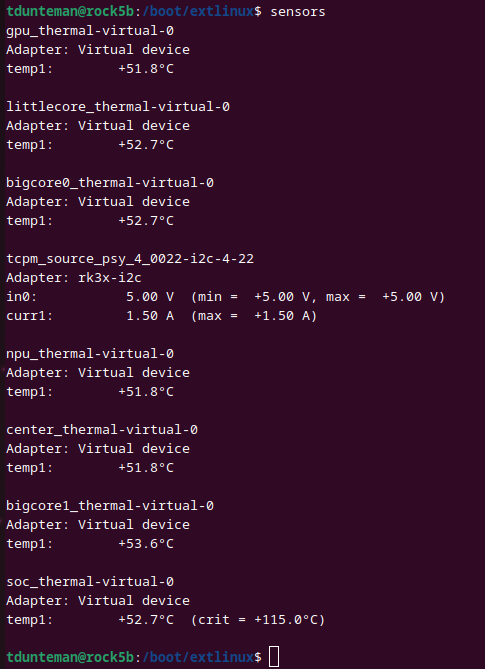
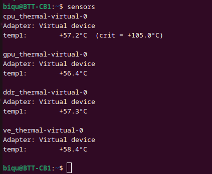
For comparison, on the left is my Rock 5B which has the Rk3588 (4x A76 + 4x A55 cores) running at 52-53°C (125-127°F) compared to 57°C (134°F). Both systems have a passive heatsink (albiet the Rock 5B has a much larger one).
Since they disabled CPU scaling in the kernel, as far as I know this means that the kernel can’t throttle the CPU if temperature reaches critical.
Ease of Use (0/2)
I would say the biggest issue with usability is overlays. There are only a handful available:
- disable_uart0: This one is pretty self explanitory and works as you would expect
- ir: This one is also self explanitory and enables the IR receiver
- light: Not clear why this is called “light”. It disables UART0, enables the bit-banging I2C as well as the PWM. Without dumping the DTBO file you really wouldn’t have a clue what this is doing
- mcp2515: This one enables the mcp2515 CAN bus, but also SPI1. Why SPI? I am not familiar with CAN buses, but from the system overlay it appears that the mcp2515 is a sub-object to spi@5011000 (SPI1).
- pwm: This enables the only available, PWM but DOESN’T disable the UART (which is on the same set of pins). So make sure you also include
disable_uart0if you use this. - spidev0_0: Not sure why this is even here, SPI0 isn’t exposed on any pins
- spidev1_0, spidev1_1, spidev1_2: These are frustrating. They all turn on SPI1 with 2x CS (0 and 1). Under the spi@5011000 device, the cs pins are set uising the “cs-gpios” field. None of these overlays edit this field. You CAN edit or remove CS pins by creating your own overlay to edit this field, but having these overlays not do what they imply is confusing.
The CB1 kernel DOES include the configfs which is a great feature to adding overlays after boot. This doesn’t however overcome the lack of documentation, pins that aren’t connected, pins that are supposed to be connected and aren’t, lack of hardware I2C, single UART and overlaping functions on pins with no alternatives available.
If you decide to buy a CB1 for something other than running a 3D printer, be prepared to write your own overlay files.
A copy of overlay files I created are available on our GitHub files here: https://learningtopi.github.io/cb1
Software Updates (1/2)
The CB1 image I downloaded is a Debian Bookworm build which is very promising. It appears that they are up to date on their distributions! Bookworm (Debian 12) was only recently released. The downside is the kernel. The CB1 is running 5.16 which was NOT a long term train (5.15 was). 5.16 stopped receiving security updates over a year ago (April 2022). The bizzare thing is that they appear to have started with 5.16.17 in August of 2022 AFTER support was ended. And they didn’t even start with the last release which was 5.16.20.
You may be able to keep the system up to date, but the kernel was out of support when they started.
Community (0/2)
I could find practically no community for the CB1. The first discussion board I found for the CB1 (https://github.com/bigtreetech/CB1/discussions) says it is abandoned (not a good start) and only has a handful of discussions from 2022. The link at the top of this discussion board linked to another discussion board (https://github.com/bigtreetech/CB1/discussions/8) that ALSO says it is abandoned. This page had a total of 6 comments and 9 replies. This just takes you to a discussion for the Bullseye minimal image (which I’m not even running): https://github.com/bigtreetech/CB1/discussions/9. Again here there was still only 25 comments and 43 replies.
Don’t expect to find a lot of community feedback for this board.
Issues
Security Groups and UDEV not setup for I2C and SPI
I mentioned under the I2C section that the biqu default user wasn’t in the i2c user group. For SPI, devices were created with only root access. I had to create the spi group, create a udev rule and add the biqu user to the spi group. While this is not extraordinarily complicated to do, if you are are not familiar with the udev rules it may take some time to setup non-root access. More mature SBC platforms have this configured out of the box ready to use.
No I2C only overlay
Also in the I2C section I called out the lack of a dedicated I2C overlay (even though it is a bit-banging software overlay and not a hardware one). The “light” and “tft” overlays turn on I2C in addition to other functions that you may or may not want. (For example “tft” also disables the HDMI port, “light” disables the only UART and enables PWM in its place.)
There is of course nothing stopping you from creating your own overlay files. The CB1 uses a boot.cmd UBOOT script that includes a check for user provided overlays. Simply create the /boot/overlay-user directory and place your compiled DTBO files here. In the BoardEnv.txt file, add a line for user_overlays. Then just add a space separated list of overlays you want to create.
Pins that don’t work (PG6, PG7, PG8, PG9)
For some unknown reason these 4 pins just wouldn’t work. They are documented in the pinout, I could reserve the pins but setting them high or low had no affect. Using my oscilliscope I was never able to get a signal on these pins. All I get is background static the same as I get on the pins that Bigtreetech marked as “not connected”. Not sure why these pins don’t work since they are listed on the schematic (https://github.com/bigtreetech/CB1/blob/master/Hardware/BIGTREETECH_CB1_V22_220812_SCH.pdf) on connector A1-100.
UART0 overlaps with TWI and PWM
The PH0 and PH1 pins are the only pins that can be used for UART0, TWI (I2C although I still couldn’t get this to work) and PWM. You get to pick one of these three functions. None of the other connected pins support any of these functions (other than running the soft I2C driver). This is severly limiting in terms of what functions are available.
UART0 doesn’t work over 115200
I was not able to figure out what caused this, but the only UART interface doesn’t work consistently (or at all) over 115200 baud. While this may work for some projects, it does show that SOMETHING is wrong design wise. Unfortunately I don’t have another board with an H616 for comparison so I don’t know if this is an Allwinner H616 chip level issue or if this is a Bigtreetech CB1 issue.
Pull-up / Pull-down Resistor Inconsistancy
I covered this above (#htoc-pull-up-pull-down-resistors). Some pins use different pull-up and pull-down resistors. This caused my input button setup on my breadboard not to function at all on certain pins. After I swapped the resistor I was using to the 3.3V rail it worked fine, it just took some time to sort out what the issue was. I have not run across this particular setup on other SoC’s. I’ll be on the lookout from now on.
Overall (5/14)
If you consider the original intended purpose of this board (to run a 3D printer), most of the issues and problems I ran across are probably non-issues. Trying to use this board as a general IOT device is far more problematic. The lack of functions exposed on pins make it extremely hard to find a good use for this device. The only 2 things that I didn’t have any major issues with was SPI (other than missing udev setup and security groups) and IR. I2C is software based, the UART didn’t work consistently (or at all) over 115200 and 4 of the GPIO’s documented in their notes wouldn’t work. There are also 6 pins that just aren’t connected to anything (on TOP of the 4 I couldn’t get to work).
All in all I would say if you aren’t planning to use this for a 3D printer I would suggest looking for an alternative. It may work for some specific use cases, but you will likely need to recompile the kernel to get CPU throttling turned back on and you have limited IO functionality.
A copy of overlay files I created are available on our GitHub files here: https://learningtopi.github.io/cb1
